A fire damper is part of the building’s overall fire safety strategy. In a general ventilation system, it closes the duct to maintain separation between fire compartments, while in a smoke exhaust system, it opens the required branch to remove combustion products. The damper’s normal and fire positions are determined by its function, the project design, and the fire automation control sequence.
A properly selected fire damper for a ventilation system must match the required fire-resistance rating of the construction through which the duct passes, the installation conditions, and the specified control scheme. Products with the same dimensions are not necessarily interchangeable: they may differ in functional design, blade position, actuator type, and permitted installation orientation.
Fire Damper Design and Purpose
A typical fire damper consists of a casing, movable blade, seals, and an actuator mechanism. Depending on the design, it may also be equipped with a thermosensitive element and position limit switches.
The damper blade changes the cross-sectional area of the air duct. Fire-retaining dampers are designed to prevent the spread of flames and hot gases, while smoke dampers connect the required areas to the smoke exhaust system. These functions should not be combined in one product unless the damper has a certified universal design.
Fire Damper Classification
The main types of fire dampers are classified according to their functional purpose, casing design, cross-sectional shape, and actuator type.
Classification criterion | Type | Features |
| Functional purpose | Normally open fire damper | Open during normal operation and closes in the event of a fire |
| Functional purpose | Normally closed smoke damper | Closed during normal operation and opens in the designated smoke exhaust zone |
Construction | Duct-mounted | Installed in the air duct |
Construction | Wall-mounted | Installed in an opening in a fire-rated wall, partition or floor |
Construction | Cassette | Used for large openings and consists of several sections |
| Cross-sectional shape | Round | Designed for round ducts |
Cross-sectional shape | Rectangular | Designed for rectangular ducts |
Actuator type | Electromagnetic | Moves the damper blade when the control signal is applied or removed |
Actuator type | Electromechanical | Controls the damper blade and may return it to its initial or protective position |
Normally open and normally closed dampers perform different functions. A fire-retaining damper is designed to close the ventilation duct, while a smoke damper opens the required branch of the smoke exhaust system. The specific operating sequence is determined by the project design and is not selected during installation.
Operating Principle of a Fire Damper
In standby mode, the damper remains in its normal operating position. When a fire signal is received, the actuator moves the blade to the required position. Position feedback is transmitted to the fire automation system.
A normally open fire damper closes when a fire signal is received. The associated ventilation equipment may then be shut down or switched to another operating mode according to the fire safety control sequence.
A normally closed smoke damper opens in the smoke exhaust zone to provide the required smoke removal path. The positions of other dampers are determined by the smoke control system design and its operating algorithm.
Some damper designs include a thermosensitive element that triggers the protective position when a specified temperature is reached. There is no universal temperature threshold for all products, so the exact value must be taken from the product documentation and project requirements.
Fire Resistance of Ventilation Dampers
Fire resistance is one of the key parameters when selecting a fire damper. The rating may include several characteristics: E — integrity, i.e. resistance to the passage of flames and hot gases; I — insulation, i.e. the ability to limit temperature rise on the unexposed side; S — smoke leakage limitation; the number indicates the time in minutes for which the specified performance is maintained under the relevant fire test conditions.
The fire-resistance rating applies to a specific product design and its tested installation assembly. The actual performance depends on the damper’s position relative to the fire barrier, installation orientation, sealing of the opening, and the adjacent duct construction.
For example, an EI 120 rating cannot automatically be transferred to another installation configuration simply because the damper itself has the same nominal characteristics. The entire tested assembly must be taken into account.
The KPU-1N fire damper manufactured by CCK TM is available with an EI 120 fire-resistance rating, as well as in an E 180 smoke-control version. The range includes round and rectangular designs with two functional configurations.
Where Are Fire Dampers Installed?
Fire dampers are installed where ventilation ducts cross:
- fire-rated walls;
- fire-rated partitions;
- fire-rated floors and other fire barriers.
Depending on the design, the damper may be installed directly within the opening or outside the fire barrier. When the damper is installed outside the barrier, the section of duct between the fire barrier and the damper blade must have a fire resistance rating at least equal to that required for the barrier.
The opening around the duct and damper must be sealed with the materials specified for the tested installation assembly. The firestop solution must maintain the required fire-resistance characteristics of the complete construction.
Fire dampers may also be installed in transit or collector ducts where required by the project, including ventilation systems serving rooms with specific fire or explosion hazards.
The exact location and number of dampers are determined by the purpose of the premises, the ventilation system design, applicable fire safety requirements, and the adopted fire protection concept. It is not necessary to install a damper at every floor, air inlet, or outlet unless this is required by the project.
Smoke dampers are installed in branches of smoke exhaust systems and at openings connecting protected areas to smoke exhaust shafts.
Fire Damper Installation
Installation must be performed in accordance with the project documentation, certificate, product passport, and manufacturer’s installation instructions.
Before installation, check:
- the required functional design;
- fire-resistance rating;
- dimensions;
- normal blade position;
- actuator type;
- permitted installation orientation.
The damper casing must not carry the load of the air duct or building structures. Ducts must be independently supported.
The installation gap must be filled with the materials specified for the tested installation assembly. The use of a fire-resistant material alone does not guarantee the fire-resistance rating of the complete damper installation.
The actuator, limit switches, and manual controls, if provided, must remain accessible for inspection and maintenance. If the damper is concealed behind a suspended ceiling or another structure, an inspection access panel should be provided where required.
After installation, the damper must undergo a complete functional test. The check should confirm:
- free blade movement;
- correct actuator operation;
- correct normal and fire positions;
- operation of position feedback;
- correct response to commands from the fire automation system.
Fire Damper Connection and Control
The electrical connection depends on the actuator type, supply voltage, current requirements, and control algorithm.
Electromagnetic and electromechanical actuators operate differently, so there is no universal wiring diagram suitable for every damper.
The control circuit normally includes both the command to move the damper and feedback confirming its actual position. Failure of the damper to reach the required position must be detected by the automation system as a fault.
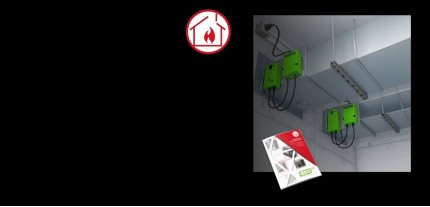
The SHTORM-K control cabinet manufactured by CCK TM is designed to control ventilation fire and smoke dampers. It can control normally open fire dampers for closing and normally closed smoke dampers for opening. The system supports automatic and manual control, status indication, and dispatch monitoring. The published configuration supports up to 44 dampers.
Cable lines and their fire-resistance requirements must be selected in accordance with the fire protection project. During commissioning, the complete sequence must be checked: control command, actuator operation, final position, feedback signal, and fault response.
How to Select a Fire Damper
When selecting a fire damper, consider the following parameters:
Parameter | What to check |
Function | Fire compartmentation or smoke exhaust |
Normal position | Normally open or normally closed |
Fire resistance | E, I, S ratings as required |
Cross-section | Round or rectangular |
Design | Duct-mounted, wall-mounted, or cassette/multi-section |
Actuator | Electromagnetic or electromechanical |
Installation | Position relative to the fire barrier, orientation, and sealing method |
Automation | Power supply, control signal, feedback, and compatibility with the control cabinet |
Maintenance | Access to the actuator, limit switches, and moving components |
The CCK TM fire-retaining damper range includes duct-mounted, wall-mounted, and cassette solutions. The specific model is selected according to the project designation, technical passport, and certificate.
The KPD-4 rectangular fire damper is designed for duct and wall installation and is available with electromagnetic or electromechanical actuators. The GMK-DU multi-blade damper is suitable for applications where the blades must not extend beyond the casing. Both products are available with an EI 120 fire-resistance rating according to their specified installation configurations.
Inspection and Maintenance of Fire Dampers
A damper may remain in one position for a long period, so the absence of visible damage does not confirm that it is fully operational.
During inspection, check:
- the casing and seals;
- free movement of the blade;
- actuator mounting;
- thermosensitive element, if installed;
- position feedback;
- the condition of moving components.
A functional test should include the complete sequence from the normal position to the fire/protective position and back, where the design allows this. The test must verify the control command, blade movement, final position, feedback signal, and response of the fire automation system.
Inspection frequency is determined by applicable regulations, the project documentation, and the manufacturer’s instructions.
The following modifications are not permitted unless specifically provided by the manufacturer:
- changing the actuator;
- removing the thermosensitive element;
- drilling the damper casing;
- applying paint or other materials to moving joints.
Frequently Asked Questions
Do all fire dampers close in the event of a fire?
No. Normally open fire dampers close to prevent the spread of fire and hot gases. Normally closed smoke dampers open in the designated smoke exhaust zone to provide a path for smoke removal.
Can a fire damper be installed next to a fire-rated wall?
Yes, if this installation method is provided by the project and the product documentation. When the damper is installed outside the fire barrier, the duct section between the barrier and the damper must provide the required fire resistance.
What does EI 120 mean?
EI 120 means that the specified construction maintains integrity (E) and thermal insulation (I) for 120 minutes under the relevant standard fire test conditions.
The rating applies to the specific damper and installation assembly for which it has been established.
Can the same actuator type be used for all fire dampers?
No. The actuator is selected according to the damper’s function, control logic, supply voltage, required normal and fire positions, and the overall automation scheme.
What should be checked after installation?
The damper should be checked for free blade movement, correct actuator operation, normal and fire positions, limit-switch operation, position feedback, and correct response to commands from the fire automation system.